Saturday 3 December 2011

TOU 4 of 4


Next is the fitting.  I would assume that any sensible modeller will have fitted the functional tie-bars, to hold the point blades at the correct distance apart, before gluing the turnout to the baseboard, and ballasting it.  I cannot lay claim to being so sensible, so I’ll gloss over the selection and fitting of your personal choice of tie-bars.
The first step in installing the TOU is to solder the dropper wires to the point blades extending down through the baseboard.  I file a small v-shaped notch in the foot of the rail in the appropriate place for the wire to sit into, to make it as unobtrusive as possible.  A lot can be achieved in disguising the wires by carefully filing back the solder afterwards.
I use dropper wires that initially are much too long.  This is to make it easy to handle them.  Any extra length is cut off afterwards and either re-used for other dropper wires or put in the “spare wire” box for future use.  It’s the sort of thing that is never wasted. 
You then slide the dropper wires into the dropper tubes of the TOU.  A tip when doing this is to have the dropper wires of unequal lengths.  That means that you fit one at a time, rather than having to try and guide two bits of very thin wire into very small holes simultaneously – a task that requires at least four hands, or an awful lot of patience.
After sliding the TOU down the wires to the baseboard, it is necessary to fix it in place.  As mentioned earlier, you could use any method to do this, although I preferred to screw it down.  In locating the TOU, I wanted to make sure that the functional tie-bar was correctly set ar one end of its travel.  To do this, I used a small bulldog clip to hold the pointblade closed on one side, and then had the functional tie-bar set to one end of the travel.
The TOU was then screwed in place.  Once this was done, I snipped off the ends of the dropper wires so that they only just protrude from the bottom of the dropper tubes.  This will reduce the chances of them being accidentally snagged and causing or being caused damage. 
It would be possible to bend over the ends of the dropper wires in the bearing tubes to provide vertical restraint on the movement of the pointblades, to prevent them rising up.  I haven’t done this, as the type of cosmetic tie-bar that I’m using will prevent the blades lifting in this plane. 


After this, the motor to drive it was installed.  Again, how this is done is down to personal taste.  As the Conrad point motor that I am currently using does not have user-definable limit travel, I have decided to use a relatively long drive rod with a sizeable omega loop in it to take up the slack and hold the point blades firmly over.


To give you an idea of the scale, the omega loop is approximately 1.5cm across the diameter.  It was formed by hand using a few tweaks of snipe-nosed pliers in the length of wire.  This is in itself a length of the 0.8mm straight brass wire referred to earlier.  I’m sure that other methods of driving the TOU would be equally, or more efficient.
The black wire that you will notice behind the operating wire is simply the earth return wire from the point motor.  I have arrange the wiring of this particular board so that the live wiring feed goes up one side of the board, through the switches and associated components – point motors and electro-magnetic uncouplers – and then returns down the other side of the board.
The wiring is kept neatly in place with a few spots of glue from an ordinary DIY hot glue gun.  This is showing one of the uncoupling magnets, not the TOU!


As always, I’m not afraid to say when things have gone wrong.  In this case, you may notice that there is an extension piece on the end of the functional tie-bar.  This was simply because I only noticed after I’d installed the TOU that I had fitted it the wrong way around.  I had left sufficient material to drill a hole to attach the operating wire at the end of the tie-bar, but this was now at the opposite end.


Rather than take off the entire TOU and re-mount it having turned it through 180 degrees, I simply decided to use a spare bit of the 60 thou plasticard glued inside the end of the square tube.
The operating wire was passed through a small drilled hole, and the end bent over to hold it in place.  At the other, point motor, end, the wire is passed through the operating arm of the motor, with it manually set over at the limit of its travel.

And that’s it.  They have now been tested and work successfully.  The longevity of them naturally remain to be tested – ask me in five years or so if I’ve had any problems.  In the meantime, if I’ve missed anything out, or I’ve been unclear, please do drop me a mail to ask.
Flymo

TOU 3 of 4


Next I moved on to the construction of the tie-bar mounts.  These are simply two cubes of the larger size plastic tube mounted on top of each other.  Two things to consider:
-          if you are cutting the tube, as I did, with a piercing saw do clean off the edges of the tube earlier to remove any plastic swarf still attached that may interfere with the smooth sliding of the tie-bar.
-          the height of the mount should be dictated by the height at with the point motor provides drive.  In the case of the Conrad motors that I am using, this is quite high and I wanted to make the connection at the same height.
These really are just one piece glued on top of the other.

After this, it was time to try the functional tie-bar out for size, to ensure that it slid freely.  I actually found that the fit was a little looser than I had expected from two adjacent sizes of tube.  However the amount of slack was not so great as to cause problems, and it gave me a bit of wiggle room for fitting them in place.


The pictures do show a slightly different order of fitting the mounts as some pictures were taken during the build of the initial TOU, and some during the batch-build of the balance of them.  The differences aren’t critical though, and just show that there are many ways to go modelling in P4.
This is the completed unit, with the functional tie-bar fitted in place.


Two points to remember, thankfully neither of which I fell foul of, but I’m sure that I came close:
-          The copper-clad strip should face the outside of the unit, so that the dropper tubes extend out over the edge.  This is probably the only critical bit of the entire process, as there needs to be clearance for the dropper wires to come down from the point-blades past the edge of the TOU, and then go through the dropper tubes.
-          If you fit both the mounts to the base first, without including the functional tie-bar, you won’t be able to slide it in to the mounts afterwards.  There simply isn’t the free room to do this.  So it does all need to come together in one go.
So that completes the building of the TOU.
(to be continued...)

TOU - 2 of 4


The first thing that I did was to make the functional tie-bars.  These will sit below the baseboard and have the task of holding the dropper wires that come down from the pointblades. 
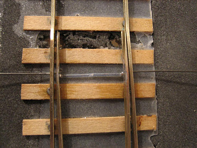
Much is made of the torsional stresses that are put in dropper wires when they are soldered in place on turnouts.  I’m not sure how much I buy into this idea, unless the section under load is particularly short.  However I saw advantages in keeping the TOU and the pointblades physically separate:
To do this, I used some small bore brass tubing.  This needs to be just a little larger in bore than the wire that you choose to use for dropper wires.  In this size, brass tube is more easily cut by rolling it back and forth under a sharp scalpel blade to create a score mark than by trying to saw it.  Using cutters will, of course, simply close up the ends of the tube, which is no good at all.
The length of the dropper tube isn’t actually critical.  I used the length shown in this picture to make both tubes for this tie-bar.


The dropper wires are very flexible, and I didn’t need to rely on the accuracy of the functional tie-bar to keep the pointblades the correct distance apart.  Nevertheless, to ease the stresses and strains of holding the pointblades in place, I made the two dropper tubes 16.5mm apart.  This was measured on the copper-clad strip, and as you can see two saw cuts made for the tube to sit in before it is soldered.  This just helped keep it located correctly and at right-angles.
As you can see in the next picture, I later cut a further gap in the copper clad to insulate the dropper tubes from each other.

In this picture you can see that all of the tie-bars have been made.  I have four turnouts on the board that I am building, so four was the number that I made.
You can also see that the first functional tie-bar has been glued to a section of plasticard square tube.  This is the smaller section – in my case ¼” in size.  This was done simply with some two-part epoxy. Again, the alignment isn’t critical, but it should be roughly central, and roughly square, to the plastic strip.
The next, rather dark, picture shows the production of the mounting plates.  These are approximately 70mm by 30mm.  You could make them larger if you wished, but I wanted to be able to fit them reasonably easily underneath the baseboard.

The small squares of plasticard that are being fitted are an extra that may not be necessary for other modellers.  The smallest woodscrews that I have available to fix the completed units to the baseboard are still too long to go through the TOU, and then into the baseboard that is made out of 6mm ply without the ends of the screw bursting through the top surface.  Therefore by putting spacing plates, the screw goes fully in but the tip will not come out of the other side.  If you used thicker baseboard, or glued the TOU down rather than screwing it, these would not be necessary.
I made provision for three mounting points for the screws.  In practice only two, at either end, have proved to be necessary.  After the spacing plates were glued in place and dry, they were drilled with 2mm holes to take the screws.  Given that plasticard is fairly soft, this was just done with a drill in a pin-chuck.  There was no need for any machine tools or suchlike.
(to be continued...)

Turnout Operating Units - 1 of 4


I’ve been asked to do a write-up of the Turnout Operating Units that I am using on my P4 demo board.  I wasn’t going to do this until they had been installed and satisfactorily operating, although I had done a “finger-driven” test of how effectively they work.
These are certainly not an original idea.  I believe that the original Protofour TOU was produced on a similar concept, using sliding plastic curtain rail to provide the base.  The main criteria that I wanted to meet were:
  • Mounted below the baseboard
  • Cheap and easy to produce
  • Robust but not necessary to be “engineered”
  • Did not need to be relied on for gauging the switch rails
Turning to the last point, my philosophy was that these TOUs would drive the switch rails with an approximation of the correct gap between them.  However for the precise gauging I am using a “semi-cosmetic” tie-bar.  I use the term semi-cosmetic, as primarily the role is to look authentic, but it will also provide the exactness of the distance between the rails that cannot be produced from a flexible drive mechanism three or four centimetres below the railhead.
The materials used are all very commonplace.  You may have them already.  If not, all of them are readily available from Derek Russan at Eileen’s Emporium, and no doubt other suppliers.  I just know that Derek definitely does have everything available as that’s where I got most of my components from!  Usual disclaimer, no connection, etc.  The list is:
  • Copper-clad sleeper strip. I had offcuts from track-building to use.
  • Fine bore brass tube.  By fine, I mean something that will take a 0.45mm brass wire down the inside and be a sliding fit.  My tube came from some left-over from a High Level Models kit.
  • Straight 0.45mm brass or nickel silver wire.  The sort that comes in 12” lengths from various sources.
  • Thick plasticard.  I used some 60 thou that I had in the drawer, but the thickness is not critical as it is used to provide a robust mounting base.
  • Two sizes of square Plastruct tube.  One that is a loose sliding fit inside the other.  The dimensions, again, are  not critical, and I believe that I used 5/16” and ¼” for my TOU. 
This is the tube that I used.  As they always say, other makes and flavours are available.  The TOU’s themselves are roughly seven centimetres in width, so you can make a number of the units from the two strips in each packet.
(to be continued...)

Friday 2 December 2011

Tie-bars fitted

And in a burst of competent soldering, all of the remaining tie-bars went easily into place :-)


That's one of them.  Tomorrow I hope to fit the dropper wires to the point blades and connect it all up...

Flymo

Sunday 27 November 2011

Lesson for today...

Retro-fitting tie-bars (or stretcher bars to give them the proper name) is *never* easy when you've already laid the track, and ballasted up to a height that interferes with fitting them under the rail.

Oh, and as you tidy up the soldering on the first one, the joint breaks.

Argh!  Enough is enough, for tonight...

Friday 7 October 2011

Wiring


A short preamble - I really don't like doing wiring.  It scares me.  Which is daft, as I've a Physics A-level, and I've re-wired an entire house before, so I should be comfortable about where the pluses and the minuses have to go.  But for some reason whenever it comes to wiring for models I have a mental block...

You may recall that it was quite a while ago that I finished track-laying on my "demo board" - this will be both a test track for my own use, and also a way of showing those interested in P4 modelling the different types of track that are available.  A while ago I fitted the power feeds to the tracks, and was able to get something running.  The next step is to fit the point motors and the uncoupling magnets.

First of all, an overview of the track-plan, drawn out in permanent marker on the top surface of the board.   Push-button switches have been fitted through drilled holes to provide the ability to just press switches along a route.  I thought that this would be easier, particularly for others that may have a play with it, than a more prototypical lever frame.  The rotary switch in the top corner is for selecting the power supply for each of the three roads.


And this is what it looks like underneath.  There are two separate power inputs - I wanted to keep the ones for the "trains" and the "track" separate.  At the moment the intention is to run this as DC, but I suppose that there is no reason why it wouldn't work equally well for DCC train control in future, if I decide to change.
At the bottom, the rotary switch feeds the three lines of track.  And at the top, the new wiring that I am now putting in.  The bus-bar has the feeds to the positive side of all of the switches soldered to it already.  The red wires are to the point motor switches; the pink ones to the uncoupling magnets.  It's probably an unnecessary distinction, but I can do it, so I did...


The track plan drawn on the underneath of the board helps me identify what is what - a tip picked up from somewhere on RMWeb I think, where it was used for a 2FS layout.  It's better if you use Templot to make it look smarter, but I ain't  that clever :-(

The next step is to install the point motors themselves.  For these, I'll be using functional tie-bars beneath the baseboard, and operating the point blades by means of wire running up through small holes.  This is the batch of  tie-bars being made out of copperclad strip.


So maybe I'll try fitting one of these tonight...

Flymo

Wednesday 28 September 2011

Bl**dy computers...

Just a quick apology if I've missed anyone's vital news...

I rely on an RSS feed to tell me when a new post has been made on a blog.  It seems that at some point in the last couple of months, one of the automatic updates to Blogspot/Windows/Antivirus/whatever turned off all the alerts for me :-(

And I was just thinking that it was because everyone was busy, and quiet...

Flymo

Saturday 17 September 2011

To complete the set...


This morning I popped a set of pickups on the Y14...

Well, actually I started the process last night by cutting and shaping a length of copperclad sleeper (I knew that the remains of those EM gauge points that I built when I was sixteen would one day come in useful...) so that it fitted between the frames.  I'm always doubly cautious and cut an over-generous gap.  It doesn't do any harm and means that there should be absolutely no chance of a short.

Here they are laid out in the correct order to be fitted.


Then they were fixed using two-part epoxy, and left to set solidly in position overnight.  This is the time that you don't want the modelling pixies to come along and give them a gentle nudge whilst you're sleeping!


Then finally a wipe over with some solder to tin the copper-clad (being very careful to get absolutely no flux on the steel tyres!) and fix the pickups in place.


For this locomotive I'm going to wait until the body is fully painted before wiring up the motor.  The reason for that is that I want to be very certain of the path of the wires before I solder them in place.  I will have to route them up the sides of the gearbox and along the top of the motor, before turning them back to the contacts.

So that can wait until I can handle the whole thing as a single unit.
Flymo


Friday 16 September 2011

Getting things moving


As a change from the painting, yesterday I decided to stop dithering and see if I could get the tram engine actually moving under its own power...

I had already glued in place some gapped copperclad board and given it a coating of solder to ensure that the subsequent work took well to it.  This is the preparation underneath the chassis, and also shows the amount of space that I have to work with.

As a reminder, the gearbox is one of the slimline High Level models which is articulated so that it fits underneath the boiler.  It is the 1:108 ratio (I think!) to ensure that the tram can creep along at an appropriately slow pace.  You can also see the guitar strings in place from the CSB suspension arrangement.


These are the pickups themselves.  Made by twisting  phosphor bronze wire (in straight packs from Eileen's Emporium, rather than battle with coils of the stuff) around a 2mm wagon axle with a slot cut in the end.  Inspiration from Morgan Gilbert in the thread here (look a third of the way down...)


 And these are them in place.  The gearbox limited the amount of space that I had available for one pair, but there is still enough flexibility for them to cope with the suspension movement.  As the tram wears skirts, I didn't have to worry about the ends of the wires being visible next to the tyres.


This is it completed.  You can see how low in the chassis the motor and gearbox sit.  It's on my short test board.  I hooked up a pentroller to it, turned on the juice, and off it went :-)

It can do with a little lubrication, and some gentle running in to aid smoothness and reduce motor noise, but it runs!


In this final shot it can just be seen through the door and window when the body is fitted.  This will be covered by the boiler.

Although this works successfully, I'm still not confident or happy with fitting sprung pickups (and this method is the best that I've tried so far) so I'm fairly certain that the next new-build locomotive that I start will be a split-chassis one.

Flymo

Friday 9 September 2011

More painting...


Someone prodded me a couple of days ago to ask how the tram engine was going. The answer is progressively through the paintshop...

Paint 001.jpg

The boiler is from the tram, and the backhead from the Y14. They will both be getting gauges, brasswork and similar picked out on them next.

The tram itself has had another coat of teak basecolour, but then washed over with a Dulux teak effect topcoat. It's shiny, but doesn't give a convincing effect of woodgrain in 4mm.

I don't want to lose more of the detail by putting another coat of base colour over the top, so will see what can be done with dry brushing and weathering...

Oh, and the tram interior will have to be painted again, as just after I completed that with a "guessed" colour of off-white, I found a reference that the GER painted cab interiors in tan. There are days when I really wish for a GER equivalent of "Great Western Way"!

Monday 29 August 2011

Through the paintshop


A couple of pictures of the other locomotives currently going through the paintshop.

First, the Y6 tram engine which this morning got the first coat of teak paint on the woodwork.  In my opinion, it's starting to look rather smart.


The teak will get at least another coat of paint before I start thinking about putting the woodgrain on the top of it.  

I also need to think about the colour of the interior.  I haven't found any reference yet to indicate what the colours may be.  I suspect that it would not be teak, as there would be a need for as much light as possible to be reflected into what would be quite a gloomy interior, with all of that boiler taking up space.  I suspect that I'll go for some shade of light stone, cream or ivory white, all with suitable weathering.

And this is the Y14, after three light coats of GER royal blue.  I feel that it's just about ready to start on the detailed paintwork of the areas of black, and then onto the detailing.  I quite like the satin finish, with perhaps a little more shine in the final varnish coat before the weathering goes on.


More to be done this afternoon :-)

Saturday 27 August 2011

Picking things up again...


It's been a while since I've made a post on Beer and Buckjumpers.  For that matter, it's been a while since I've had chance to do any proper modelling.  In the meantime we've decorated our study, and one of the spare rooms at home, so I can't really say that I've been idle.

However this morning I had some peaceful time, and the opportunity to pick up a smaller paintbrush.  I'm pleased to have been able to make some progress towards finishing the Pug.  I was very pleased that it ran successfully on the Pampisford test day back in June (full story here: [click link] on the Scalefour Society Forum) although it's appearance in the rather bright basecoat probably scared the horses!


So this morning I donned the white cotton gloves, and picked up (very well shaken) black paint and a size 1 paintbrush, and started.  I definitely needed the first strong coffee of the day to steady my hand, but the knack soon returned, and I've made a start at blocking in the colours.


What I'm aiming for is the picture in the background...  Much weathering to be added after the initial painting is done!  I've cried off the panelling and reverse corners on the cab for the moment, but they will probably be done next, when I have a little better light - although I see that the sun has just come out :-)

I've also noticed that I've forgotten to add a replacement smokebox door handle.  The original moulded plastic one was carved off.  I'll leave that for the moment, and hopefully remember to put a new turned brass one on when the majority of the painting is completed.


Monday 30 May 2011

Useful little tools...

Following up the suggestion of "Liquid Reamer" that was made by Buckjumper to help keep my old and neglected airbrush clean, I wandered along to chat with Derek Russan at Eileen's Emporium whilst I was at Railex this weekend.

Derek does stock Liquid Reamer :-)

But he'd just sold out :-(

It must be the power of suggestion from the web ;-)

However what he did have (and I think have recently come into stock, as I don't recall seeing them before) are a set of tiny brushes, that are perfect for cleaning out paint bowls and nozzles on an airbrush:


At only £3.50 for the set, they seemed like an absolute steal.  But that would be a bit rude, so I bought a set instead.  If I get some more modelling done on this Bank Holiday, they may well be getting a good usage later this week.

Flymo

Saturday 21 May 2011

Yuck!

Hmmm... You think that you've got your airbrush clean, and then...

After the last bout of use (see previous post on painting the Pug) I thought that I'd cleaned my airbrush out fairly well. However the action of the trigger was still a little "sticky" so I thought that it merited a little more attention if I was going to get decent results next time that I wanted to use it.

So an old jam jar that is surplus from my wife's stockpile (she funds her sidecar racing by selling homemade jam - just don't ask...) and drop all the bits in it. Fill up with cellulose thinners and give a good shake.

The thinners is now a dirty dark yellow colour, and the parts clearly still aren't entirely clean. I'll give them a good going over with cotton buds in a while.

Attachment:
yuck.jpg
yuck.jpg [ 87.75 KiB | Not viewed yet ]


But it's surprised me how much paint has built up inside and still hadn't come out through "normal" cleaning. I think that I'll be doing this more frequently in future...

Flymo

Thursday 19 May 2011

Off on the right foot

It's been awhile since I looked at the Ulpha Light Railway.  I tucked it away safely in the back of my garage (at the opposite end to the birdfood, so hopefully our resident woodland creatures don't mistake the scenery for a snack...) and have left it there until I feel that I can get the whole thing out and erect it for a couple of days.

However I have started work on the restoration of the infrastructure.  When I first brought it home, and did a test erection in the garage, I had no end of trouble getting it levelled out.  After a life of twenty years, even though each trestle leg was fitted with screw-adjustable feet, I found that they were dirty, corroded, jammed, or a combination of the three.  Something needed to be done to make them workable again.

My first thought was just to replace them, so I had a quick look on the web.  There are a number of suppliers out there, ranging from Screwfix to model railway specialists.  But generally the price per leg was £3-4 for each foot, and I needed 16 of them.  I didn't really want to pay around fifty quid if I could avoid it.

So on a sunny evening, I sat down and unscrewed them from the bottom of the trestles.  That in itself took some time, as the screws had also suffered from time.  Having got the feet off, I used spanners and a bit of brute force to separate them into separate components.  The locking nuts were discarded, as I'd already got replacement stainless steel ones from Screwfix - strongly recommended for this sort of stuff.

To clean all the dirt and clag off them, I popped all of the feet, and the mounts, in my ultrasonic bath with plain water and gave them a few cycles.  Then they went into a cooling oven (after dinner...) to dry them out thoroughly.  After that, the restoration could begin.

For working on motorbikes, I have a set of taps and dies:


So I ran the feet through the dies to clean up the threads and get rid of residual gunge and corrosion.  Now they are all back together, with new nuts, and a touch of grease on them, and I hope that they'll give many more years of service.


Next, onto the trestles themselves...


Wednesday 27 April 2011

It's a bit bright!

But nothing that a bit of weathering won't tone down.  

As this Pug is now transformed for industrial use, then I don't need to slavishly follow a prototype livery.  Which is some respects is a shame, as I was quite looking forward to seeing it in L&Y black with red lining.  However I do have a second High Level chassis kit in the drawer, and a spare body, so I can always do that in the future...

This is the base coat - a Humbrol medium red - sprayed on over the black original livery.  I took it carefully to build up the colour in thin layers without runs or other blemishes.


You see what I mean about bright!  The masking will cover off most of the motion and wheels so that I don't have to clean them off to a great extent.

The next tasks will be the footplate/chimney/etc in black, and then on with the black panels around the red, and finally into some very fine orange lines, complete with reversed corners.  There's nothing like a challenge!

Saturday 23 April 2011

Ready for the finish

Well, the weather is perfect for gardening, or DIY, or painting small L&Y locomotives...

So having run the Pug successfully at the North London Group meeting last Monday night, it is a good time to fire up the airbrush and put a livery on it.  However, before I do that, I thought that I'd post a couple of pictures of the finished work from the High Level Kits chassis and conversion kit.  I really can't recommend this too highly for its level of detail and precision of assembly.

First of all, showing the cab detail.  All of this is new in the kit, and replaces the motor in the Dapol original!


And the other side.  The lettering has been rubbed down with a glassfibre brush to help avoid it showing through the top-coat when it is put on.  More of that when the painting is underway...


The final task before painting will be to mask as much of the wheels as possible, to avoid gumming up the mechanics.  Let's hope that I'm successful in it :-)
Flymo

Sunday 17 April 2011

Making a stand

That's what I'll be doing later today...

First thing this morning I decided to fire up the airbrush and put a coat of self etch primer on the chassis of my Y14.  So I set up the spray booth, turntable, mixed the primer, loaded the air-brush...

And promptly fired the chassis to the back of the booth!  Ho hum...

A _gentle_ application of primer seems to have done the trick, but I really should knock something properly designed for the task.  I'll dig out a couple of offcuts of timber from the garage and see what I can do with some bent coathangers.

For now, I'm off to take the motorbike out for some background photos of research for restoring Ulpha Light.

Flymo

Monday 11 April 2011

Scalefour North

What an absolutely superb show!  I was so pleased to have made it, after dropping my better half off at Mallory Park for a spot of sidecar racing...  Certainly the best selection of layouts that I've seen at Scalefour North.  Every one of them interesting, and in a different way.

My personal favourite was Horselunges, because it's exactly the sort of rural shunting puzzle that I'll build myself one day!  In close seconds were Lee on Solent and Longcarse West, both of which I can stand and watch for hours. 

I hope to see all three of these again in the near future - Gordon Ashton mentioned that Horselunges was invited to appear at the Pendon show soon, and I encourage everyone to go a see it.

The trade support was excellent as well.  I don't think that there was a single moment when there wasn't a crowd around the Hogh Level Kits stand, but at least Chris hadn't run out of his new "spacesaver" bearings by the time that I reached him :-)

My only regret was that because my diary was so crowded I didn't get the opportunity to make a weekend of it :-(

Maybe next year...

Friday 1 April 2011

Old furniture and new vices...

I haven't had much chance to spend time online since enjoying the Modeller's Weekend at Missenden.  I didn't actually post from there as it seemed much more important to actually get some modelling done :-)

The last couple of weeks have been very busy with work, and other matters, but I have been doing more modelling in the background.  One of the things that I learned at Missenden was that my toolkit was deficient.  Those who saw me unpack, and produce all manner of oddments on request throughout the weekend may find that hard to believe but it's true.

One of the things that helps Tim Watson, our group tutor, produce such superb 2mm scale models is that he has a precision to his metal work that borders on that of a watchmaker.  A lot of this, such as filing is done using a vice to hold the workpiece.  In contrast, I just use the edge of the bench, or hold it in my fingers.

So when he suggested that a proper jewellers' vice would help enormously, then I saw the common sense in it. Tim advised not to waste money on a cheap one from one of the tool suppliers that you get at exhibitions, but to invest in a proper one from a watchmaker's suppliers like Shesto.

On returning from Missenden, I searched for the type that he recommended, and a few other bits and pieces that I needed, and ordered them online from Shesto.  Fortunately, as a Scalefour Society member, I get a 10% discount on everything ordered from Shesto, so I've already saved nearly half of my annual Society subscription.  Which is nice :-)

When the package arrived, i had a good look at the vice, which is a lovely engineered piece of work, and also demountable via a clamp and lever from its base.  I decided to place it on the right hand edge of my bureau cum workbench, where it will be easy to use.  Having it able to be removed means that I can take it off and still close the lid to turn the workbench into a normal piece of furniture again.

I marked out the boundary of the base, to be inset into the timber, and attacked it with a couple of chisels...


That is the base of the vice at the top of the picture, being checked for size.  I took a bit of care to get the hole nicely trimmed to fit tightly, and ensure that the bottom surface was smooth.  I raided my stock of screws in the garage for some cabinet-makers screws that would fit flush - my last ones, so I must remember to get a further stock - and then cleaned everything up and tried it for size:


The result is a total success.  Sturdily mounted, and able to be tidied away.  I haven't tried it in anger yet, but I'm sure that I will soon...